Read the earlier parts: Part 1, Part 2
Weapons Integration:
The F-35 is being designed to be able to carry a wide array of weapon to accomplish various types of missions. These weapons can be carried either internally or externally. The internal weapon bays significantly reduce the Aircraft’s radar signature.
When stealth features are not needed, the F-35 is also provided with external hard-points to be able to carry ordnance externally, significantly increasing its payload capacity. The F-35’s weapon bay can accommodate a wide array of ordnance that can be easily loaded by the ground crew. The F-35 can carry up to 6 Tons of payload during each sortie.
Autonomic Logistics (AL):
Autonomic Logistics (AL) is a seamless, embedded solution that integrates current performance, operational parameters, current configuration, scheduled upgrades and maintenance, component history, predictive diagnostics (prognostics) and health management, and service support for the F-35. Essentially, AL does invaluable and efficient behind-the-scenes monitoring, maintenance and prognostics to support the aircraft and ensure its continued good health.
The autonomic logistics system, as the F-35 system is called, will monitor the health of the aircraft systems in flight; downlink that information to the ground; and trigger personnel, equipment, and parts to be pre-positioned for quick turnaround of the aircraft. Ultimately, this automated approach will result in higher sortie-generation rates. Through a system called prognostics and health management, computers use accumulated data to keep track of when a part is predicted to fail. With this aid, maintainers can fix or replace a part before it fails and keep the aircraft ready to fly. Like the rest of the program, the autonomic logistics system is on a fast track. It has to be available to support the air vehicle during operational test and evaluation.
Propulsion System:
The propulsion systems to be used on the F-35 are the most powerful turbofans to be used in a fighter aircraft. Two different, but interchangeable systems are being developed – the F135, by Pratt & Whitney [P&W] and the F136, by a team formed by General Electric and Rolls-Royce. Both the F135 and F136 will use common exhaust and Lift systems. Two major variants of the engine are being developed by both the design teams – one variant would power the CTOL [F-35A] and CV [F-35C], whereas the other variant would be equipping the STOVL [F-35B].
The F135 engine consists of a 3-stage fan, a 6-stage compressor, an annular combustor, a single stage high-pressure turbine, and a 2 stage low-pressure turbine. P&W is using cutting-edge technology to provide the F-35 with higher performance than conventional fighter aircraft.
The F136 engine consists of a 3-stage fan, 5-stage compressor, a 3-stage low-pressure turbine section and a single stage high-pressure turbine.
Engine Characteristics
Conventional Take Off and Landing /Carrier Variant
CTOL /CV Engine Design
| Maximum Thrust | 191.3kN |
| Intermediate Thrust | 128.1kN |
| Length | 5.59 meters |
| Inlet diameter | 1.17 meters |
| Maximum Diameter | 1.30 meters |
| Bypass ratio | 0.57 |
| Overall pressure ratio | 28 |
Short Take Off and Vertical Landing
STOVL Propulsion System Design
| Maximum Thrust | 191.3kN |
| Short Takeoff Thrust | 165.9kN |
| Hover Thrust | 175.3kN |
| Main Engine | 69.837kN |
| Lift Fan | 89.964kN |
| Roll Post | 16.458kN |
| Length | 9.37 meters |
| Inlet Diameter | |
| Main Engine | 1.17 meters |
| Lift Fan | 1.27 meters |
| Maximum diameter | 1.3 meters |
| Bypass Ratio | |
| Conventional | 0.56 |
| Powered Lift | 0.51 |
| Overall Pressure Ratio | |
| Conventional | 28 |
| Powered Lift | 29 |
Short Takeoff and Vertical Landing [STOVL]
The propulsion system of the F-35B variant of the aircraft is truly ground-breaking as it is going to be equipped with STOVL capabilities, making it the first operational STOVL-capable aircraft in the world that is also supersonic in cruise. The other existing STOVL-capable aircraft, the Harrier can only fly at sub-sonic cruise speeds, making it extremely vulnerable to attacks from enemy fire.
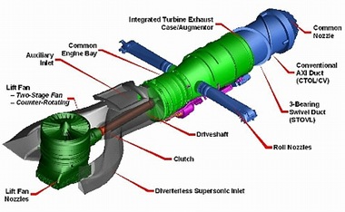
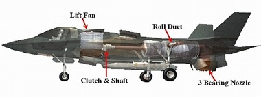
The path that Lockheed Martin has taken to achieve the STOVL capabilities is also quite revolutionary. Unlike the vectored-thrust approach taken by the Harrier, the F-35B would be fitted with a vertically-orientated Lift Fan system developed and patented by Lockheed Martin. The Lift Fan would be powered by a 2-stage low pressure turbine on the engine. The Lift Fan would generate a column of cool air that would generate thrust of nearly 89kN using variable inlet guide vanes to modulate the air flow and therefore the thrust. During STOVL operations, the Lift Fan engages the Engine by means of a shaft and clutch arrangement and a "D"-shaped nozzle provides the thrust deflection. The D nozzle consists of four sections with the final part containing fixed vanes. The Lift Fan is capable of supporting nearly half the weight of the Aircraft. A unique feature of the Engine design is the Auxiliary inlet for the engine provided above the fuselage behind the Lift Fan that provides the extra air required for inducing hover conditions.
A three-bearing swivel nozzle [3BSN] can deflect the thrust from the engine exhaust from the conventional horizontal direction to just forward of vertical, thus providing additional downward thrust to support the Aircraft during its vertical movement. Two Roll nozzles provided by the sides of the engine perform the task of Roll control. Yaw control is achieved by swivel nozzle yaw. Pitch control is affected via Lift Fan/engine thrust split.
While operating in short take-off mode, the Lift Fan inlet and the exhaust doors open and inlet guide vanes close down to minimise air flow and the clutch is engaged. As clutch plates synchronise, the Lift Fan gear drive accelerates and is brought to input speed. The inlet guide vanes are then opened to bring the Lift Fan up to speed and the D nozzle is rotated down to vector the Lift Fan thrust aft; with the main engine thrust, this helps accelerate the aircraft forward and upward. After transitioning to wing-borne flight, the inlet guide vanes are again closed down to reduce the air flow through the Lift Fan, the clutch is disengaged, the nozzle is retracted, and the inlet and exhaust doors are closed.
While operating in vertical landing mode, the aircraft decelerates and the Lift Fan inlet and exhaust doors open. The Lift fan is brought up to speed as described above, but the D nozzle is left retracted to its fully vertical position. The clutch is designed to engage in 3-7 seconds. A mechanical lock-up device then ensures that the clutch does not slip once the Lift Fan is fully engaged. The clutch plate absorbs energy during engagement and dissipates it using cooling air before its next engagement.
Simple configuration changes enable the conversion of the F136 from a CTOL/CV to a STOVL engine. Engine controls and software will differ among the various configurations. For the STOVL variant, the fan duct incorporates a bypass offtake system for aircraft roll control. A shaft is attached to the engine's low-pressure rotor. The axisymmetric nozzle is replaced with the 3BSN.
The Lift Fan approach to STOVL has four distinct advantages: -
-
The Lift Fan thrust can be de-coupled from the aircraft engine during horizontal cruise, thereby enabling the availability of full power of the engine to the cruise.
-
The amount of thrust produced by the Lift Fan system greatly exceeded the additional weight of the system.
-
The Lift Fan produced a downward thrust of cool air that mixed with the hot exhaust gases directed by the 3BSN, thereby significantly lowering exhaust temperature and hence creating more benign ground environment during hover.
-
The oxygen-depleted hot exhaust from the Harrier’s exhaust nozzles often entered the main inlet of the aircraft, thereby cutting oxygen supply to the engine and causing great operational difficulties. The downward-acting cool air column created by the Lift Fan greatly mitigates this problem.
When not carrying any onboard ordnance, the downward thrusts produced by the aircraft’s propulsion system is enough to lift off the ground and then switch to cruise mode [horizontal travel].
Read the remaining part: Part 4Godpseed
![F-35 Joint Strike Fighter [J.S.F] F-35 Joint Strike Fighter [J.S.F]](http://lh5.ggpht.com/shubhpicasa/SQVwpuwpdMI/AAAAAAAABDM/gggt6mGgx-U/20081027jointstrikefighter08_thumb%5B5%5D.jpg?imgmax=800)

